Assembly Instructions
Step-by-step guide to assembling your Data Walker device.
Before You Begin
Ensure you have all components and tools ready. Work on a clean, static-free surface to protect electronic components.
Required Tools
- Small Phillips screwdriver
- Soldering iron and solder (for sensor wiring)
- Wire strippers
- Multimeter (for testing connections)
- Hot glue gun (optional, for securing cables)
Step 1: Prepare the Enclosure
- If 3D printing, ensure all support material is removed
- Test-fit the ESP32 board in its mounting position
- Verify the display window is clear
- Check that the USB port aligns with the enclosure opening
Step 2: Install the ESP32
- Place the ESP32 board on the mounting posts
- Secure with M2 screws (do not overtighten)
- Connect the OLED display via I2C header
- Route cables away from the USB port
Step 3: Wire the RJ22 Jack
- Strip approximately 5mm from each wire end
- Tin the wire ends with solder
- Connect to ESP32 pins:
- Pin 1 (Red): 3.3V
- Pin 2 (Green): GPIO 34
- Pin 4 (Yellow): GND
- Secure connections with heat shrink tubing
Step 4: Install the Display
- Position the OLED display in the window
- Secure with a small amount of hot glue on corners
- Ensure the display is level and centered
- Connect the I2C cable to the ESP32
Step 5: Close the Enclosure
- Route all cables neatly
- Check no wires are pinched
- Attach the enclosure lid with screws
- Test the USB port is accessible
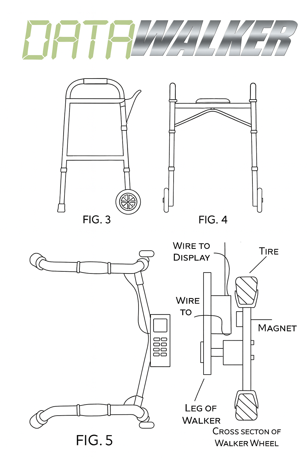
Step 6: Prepare the Wheel Sensor
- Mount 3 magnets evenly spaced (120° apart) on the wheel
- Use adhesive or drill shallow recesses
- Ensure all magnets have the same pole facing outward
- Attach the Hall sensor bracket near the wheel
- Position sensor within 5mm of the magnet path
Next Steps
After assembly, proceed to flash the firmware and run the self-test to verify your assembly.