Wiring Diagram
Complete wiring reference for connecting all Data Walker components.
Circuit Schematic
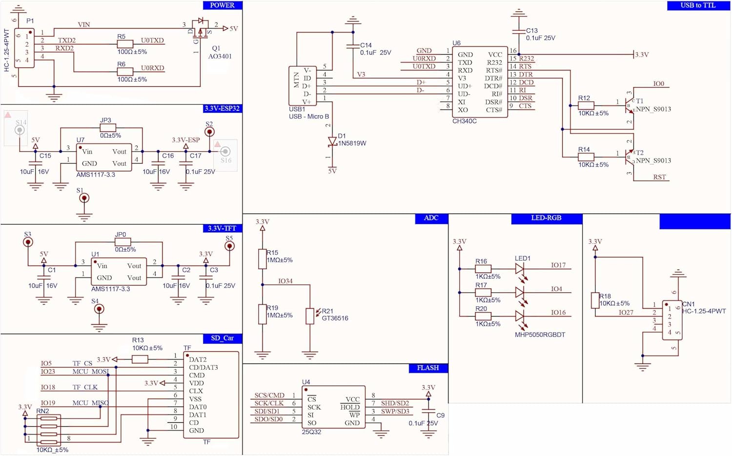
ESP32 Pin Assignments
| ESP32 Pin | Function | Connected To |
|---|---|---|
| GPIO 34 | Hall Sensor Input | RJ22 Pin 2 (Signal) |
| GPIO 21 | I2C SDA | OLED Display SDA |
| GPIO 22 | I2C SCL | OLED Display SCL |
| 3.3V | Power | Hall Sensor VCC, OLED VCC |
| GND | Ground | Hall Sensor GND, OLED GND |
| GPIO 0 | Button 1 | Menu/Select (optional) |
| GPIO 35 | Button 2 | Back/Cancel (optional) |
RJ22 Connector Pinout
The Hall sensor connects via a 4P4C (RJ22/RJ9) connector with a coiled cable:
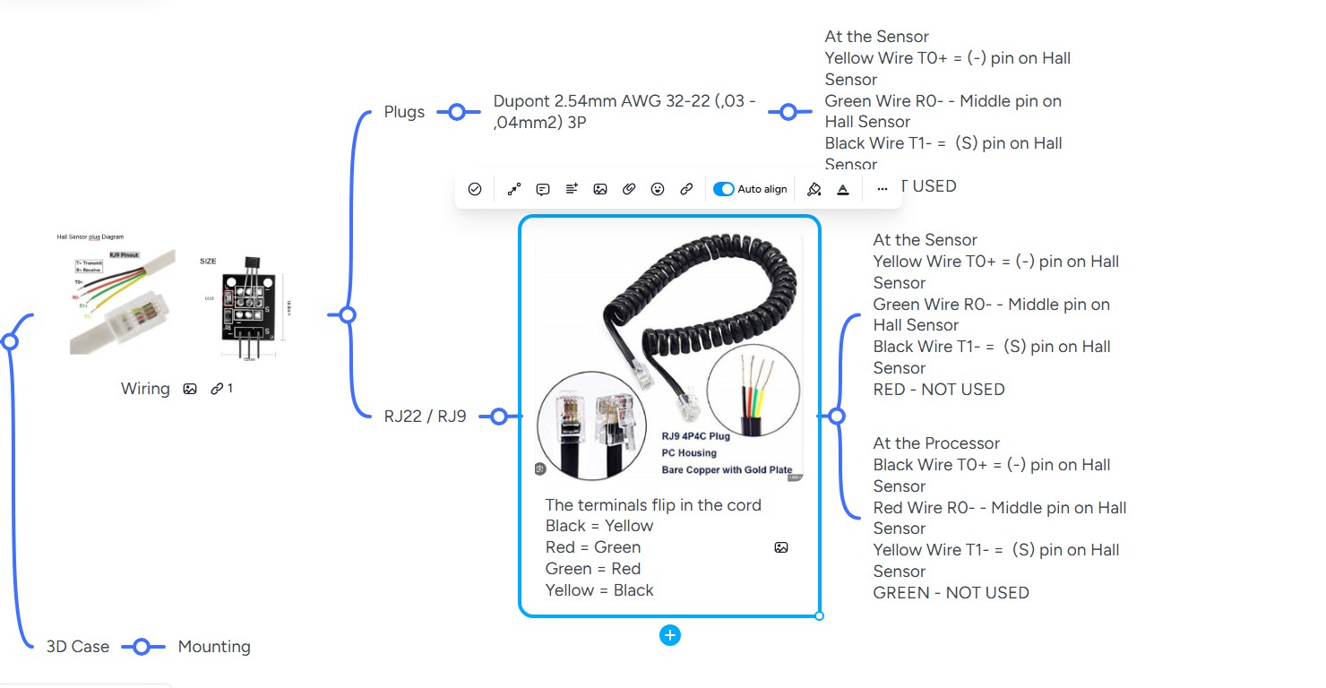
Wire Colors Flip in Cable
The terminals flip in the RJ22 coiled cord. At the sensor end: Yellow=T0+, Green=R0-, Black=T1-. At the processor end: Black=T0+, Red=R0-, Yellow=T1-. Always verify with a multimeter.
| RJ22 Pin | Wire Color | Function |
|---|---|---|
| 1 | Red | VCC (3.3V) |
| 2 | Green | Signal (to GPIO 34) |
| 3 | — | Not connected |
| 4 | Yellow | GND |
Wire Colors May Vary
RJ22 cables may use different wire colors. Always verify with a multimeter by checking continuity from each pin to its corresponding wire.
I2C Address
The OLED display uses the default I2C address:
0x3CPull-up Resistors
The I2C lines require pull-up resistors. Most OLED modules have these built-in. If your display does not, add 4.7kΩ resistors from SDA and SCL to 3.3V.
Hall Sensor Wiring
The Hall sensor (SS41 or equivalent) has 3 pins:
- VCC: Connect to 3.3V (through RJ22 Pin 1)
- GND: Connect to ground (through RJ22 Pin 4)
- OUT: Connect to GPIO 34 (through RJ22 Pin 2)
GPIO 34 has an internal pull-down resistor. No external resistor is needed.