Hardware Components
Overview of the Data Walker hardware components and their specifications.
Core Components
ESP32 Development Board
The brain of the Data Walker. We use the ESP32-2432S028R development board with integrated touchscreen:
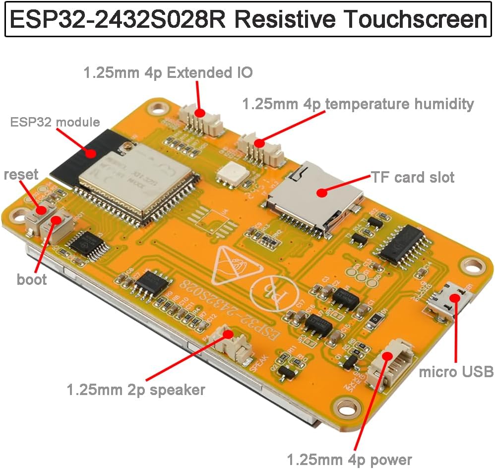
- Dual-core 240 MHz processor
- 4MB Flash memory
- 2.8" resistive touchscreen display
- TF (microSD) card slot for data logging
- Micro USB for programming and power
- 1.25mm JST connectors for power, speaker, and extended IO
- Built-in WiFi and Bluetooth (future features)
Hall Effect Sensor
A digital Hall effect sensor detects magnets as the wheel rotates:
- Model: A3144E/A3144
- Type: Digital output
- GPIO: Pin 35
- Trigger: RISING edge
- Debounce: 50ms
- Operating voltage: 3.3V
Wheel Configuration
The wheel and magnet configuration determines measurement resolution:
- Wheel diameter: 125.6mm (4.94")
- Wheel circumference: 394.5mm (15.53")
- Magnets: 3 neodymium (6mm × 3mm disc)
- Magnet spacing: 120° apart
- Distance per rotation: 1.30 feet (394.5mm)
- Resolution per pulse: 131.5mm (5.18")
Measurement Resolution
Each magnetic pulse represents 131.5mm of travel, providing ±65.75mm theoretical precision. At 10 meters, this translates to approximately ±1.3% accuracy — suitable for clinical gait assessment.
Display
The integrated 2.8" TFT touchscreen provides the user interface:
- Resolution: 320×240 pixels
- Type: XPT2046 resistive touchscreen
- Interface: SPI with ILI9341 driver
- Update rate: 10 Hz display, 1 Hz speed calculation
- High contrast for clinical visibility
- Touch-based menu navigation
Power
External USB-C power bank provides extended runtime:
- Input: 5V USB-C
- Operating current: 150-200mA typical
- Battery: 5000mAh external power bank
- Runtime: 8-10 hours continuous use
Enclosure
The 3D-printed enclosure protects components and mounts to the walker:
- Material: PETG or ABS for durability
- Mounting: Clip-on design for standard walker frames
- Access: USB port accessible for charging/programming
Connections
The Hall sensor connects to the main unit via an RJ22 (4P4C) cable:
- Pin 1: VCC (3.3V)
- Pin 2: Signal
- Pin 3: Not connected
- Pin 4: GND